Assembly
Body
The custom parts are printed in PETG, no supports required. The printable files can be found at Prusa Printers. To assemble Lepta’s body, we need the lower body, battery cage cover and the LiPo Battery
First the Battery is placed in the lower body. The body part is symmetric, so orientation does not matter.
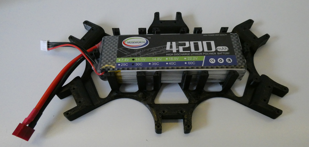
The battery cage cover is screwed on top of the battery. The 4 holes with a small standoff are intended for the raspberry and therefore left without a screw for now.

Then the powered Molex connectors are screwed into place to the left and right of the battery.
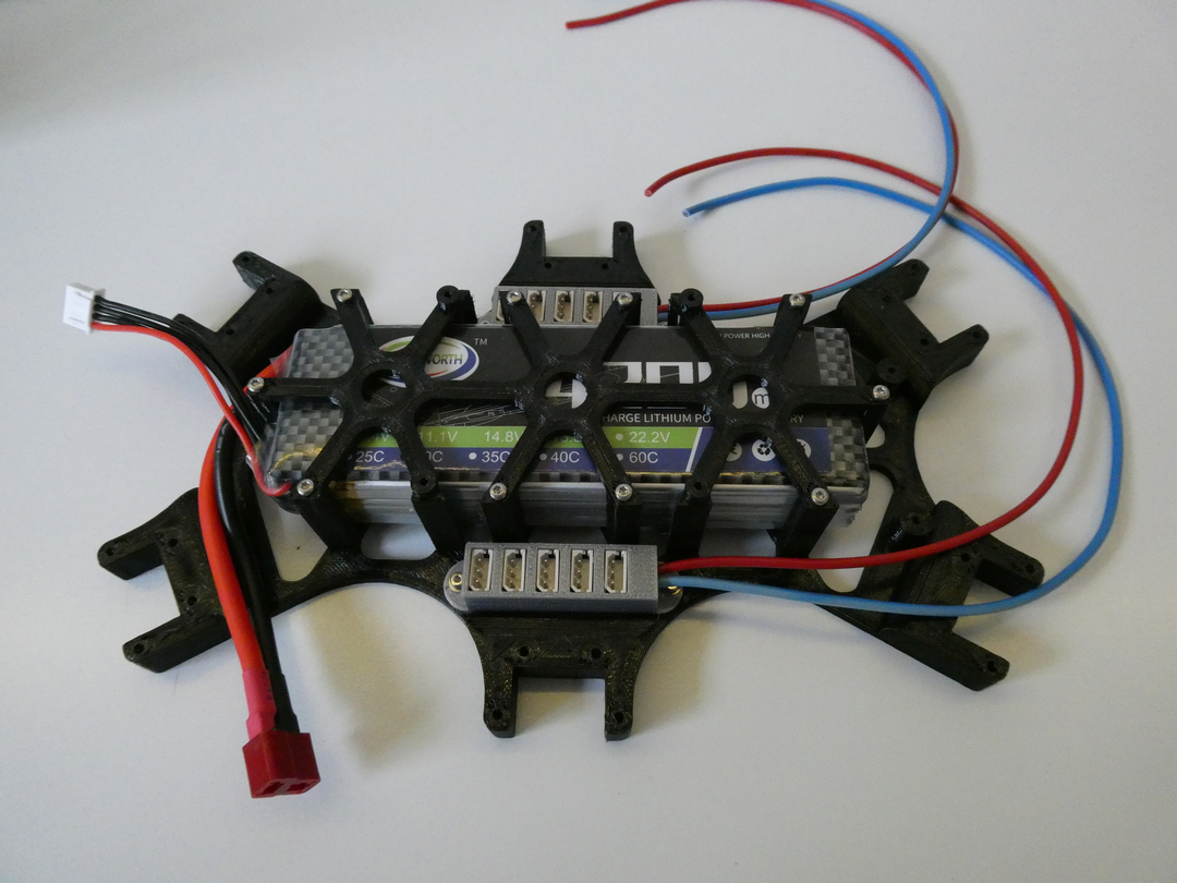
Also you can screw on the U2D2 to the standoff at the front of the robot. This concludes the body assembly for the moment.
Before the upper part of the body can be completed the legs have to be assembled.
Legs
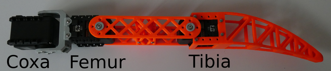
A complete leg consists of coxa, femur and tibia as shown in the image below (comment in rst-file). Coxa and Femur require some pre-assembly, before they can be incorporated in the leg.
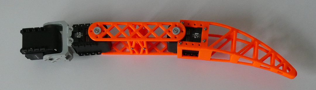
The coxa is assembled by connecting the P04-F3 and the P04-F2 like this using 4 pcs M2x6 mm screws with 4 pcs M2 nuts.

The two parts of the femur are connected with 4 pcs M2x6 mm screws directly into the plastic without a nut.
Now the servos can be installed between tibia and femur, femur and coxa, and to the other end of the coxa. Wherever a servo is connected to the custom parts be sure to use the BPF-WA/BU on the opposite side than the Servo Horn.
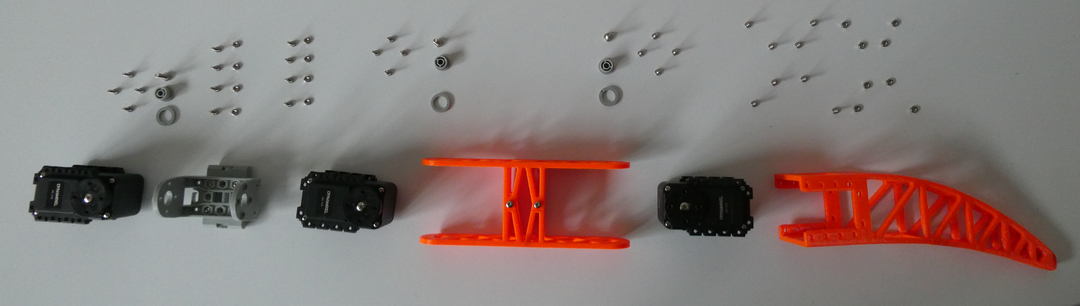
This exploded view of the leg shows you the screws and parts, that you need for every joint. Be sure to keep the orientation of the servos the same, otherwise you would have to change the control. (All screws in the image are M2x6 mm)
Servo Numbering
To keep track of the individual servos, I name them identical to the leg segment, that they control. Thus the up most servo in the leg, that controls the coxa, is also referred to as coxa (comment in .rst).
Each Servo requires an unique ID in order to be addressed by the system. This ID can be assigned using the Dynamixel Wizard.
Connect each Servo individually to your PC using the serial interface, and assign these IDs:
Leg ID |
Coxa |
Femur |
Tibia |
|---|---|---|---|
Right Rear |
8 |
10 |
12 |
Right Middle |
14 |
16 |
18 |
Right Front |
2 |
4 |
6 |
Left Rear |
9 |
11 |
13 |
Left Middle |
15 |
17 |
19 |
Left Front |
3 |
5 |
7 |
Connect the servo motors on each leg in series (?) together, from femur to tibia to coxa.
Body revisited
After all 6 legs have been assembled they are attached to the lower body, by using 4 pcs M2 x 6 mm screws with Nuts.
Connect the 6 Coxa motors with the Molex connectors (3 on each side).
Now screw the raspberry pi into place.
Before we mount the body top, it is the time to finish the cabling.
Cabling
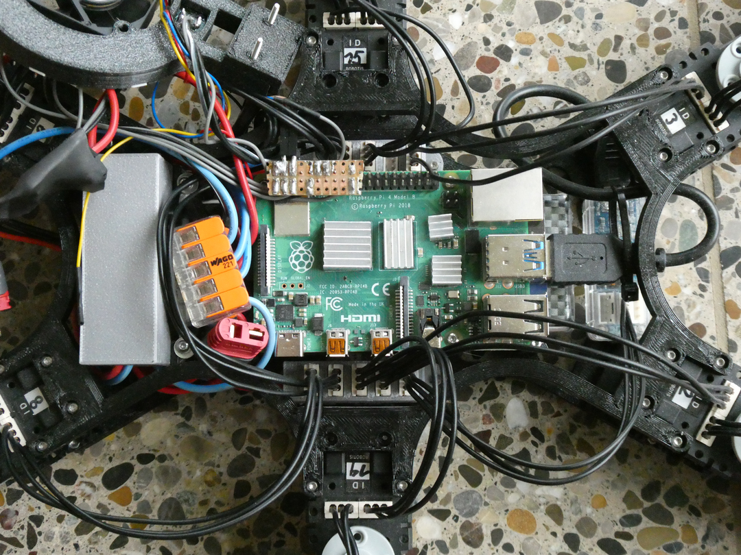
This image shows the body with the Raspberry Pi installed and all major cable runs connected.
In a first step, we supply power to the Raspberry Pi and the legs and connect the servo controller. The connections are done as shown in the schematic below.
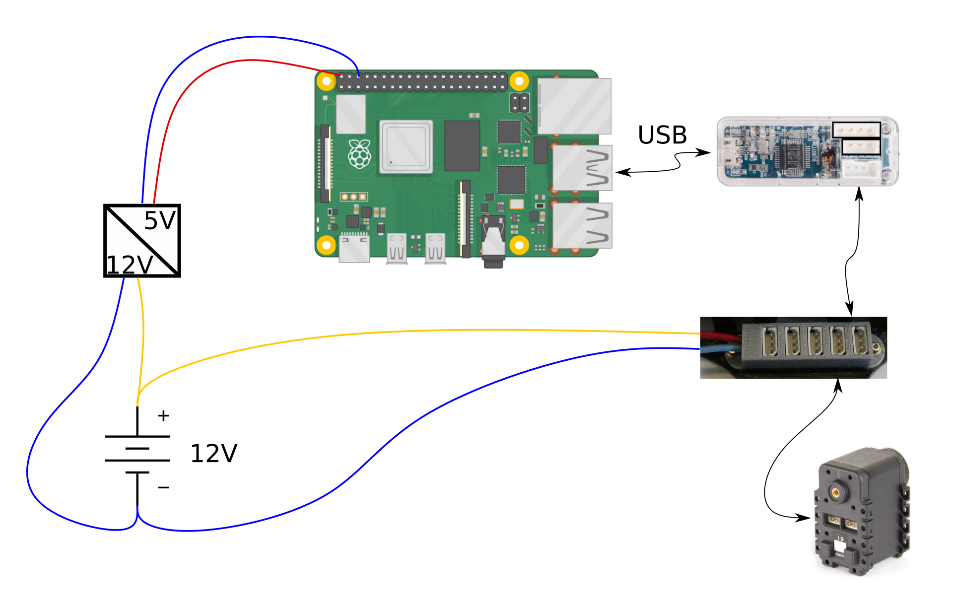
The battery is connected to the DC/DC converter. The DC/DC converter should supply enough current for the raspberry pi, it is recommended to provide 3A.
The Raspberry Pi receives power from the 5 V outputs of the DC/DC converter to its power pins 4 (5 V) and 6 (GND).
To supply power to the legs, we connect the powered Molex connectors to the 12 V supply.
Finally, connect the servo controller to the Raspberry Pi and the Molex rails.
Supervisor Cabling
These parts are not mandatory for the robot, but can be a big help. I would recommend to use at least the INA260 or a similar device to supervise the battery and power delivery.
The schematic below shows the power and data connections for the supervisor
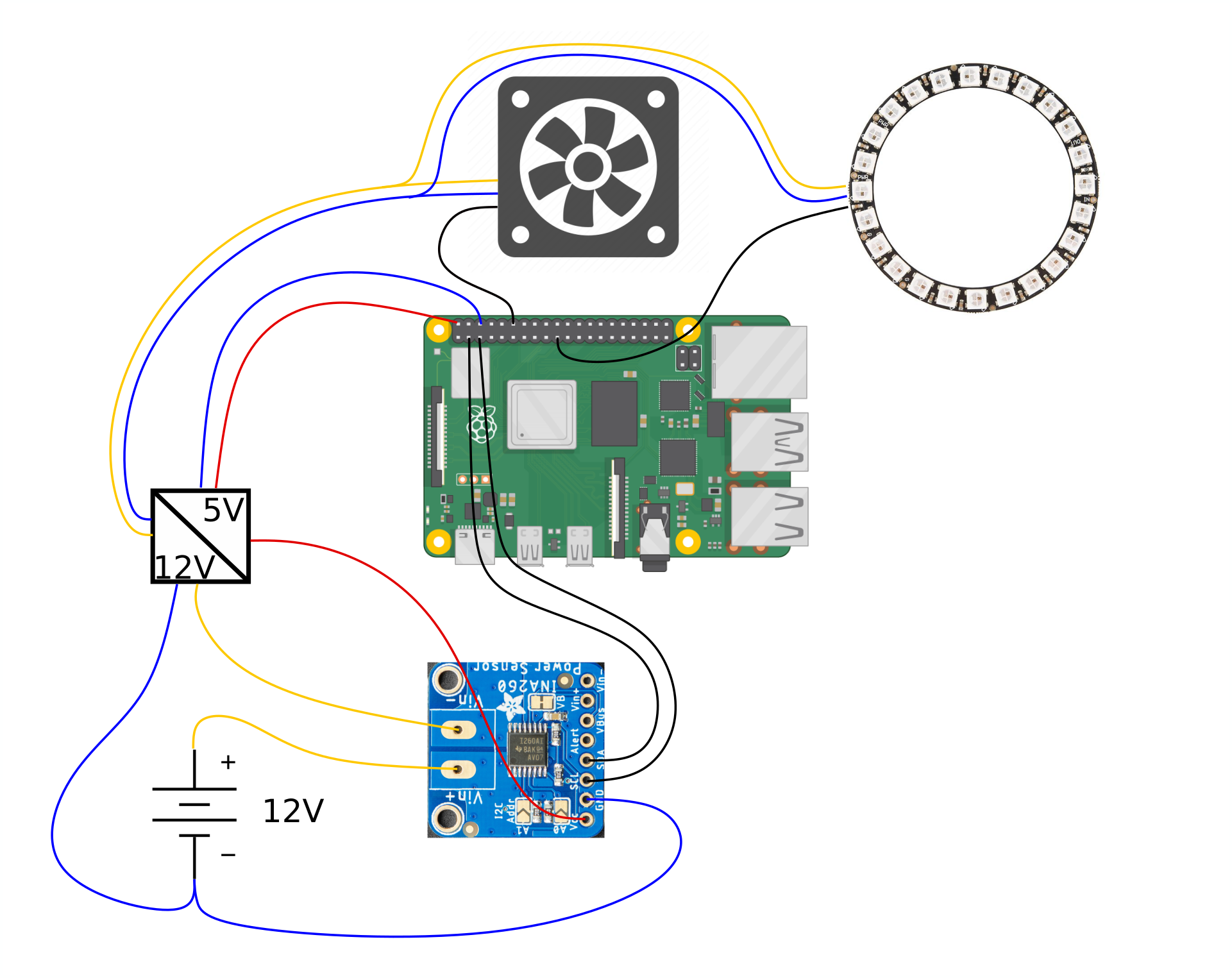
Connect power as shown above.
For the data runs to the GPIO pinout header of the Raspberry Pi, follow the pins described in the table below
Part |
GPIO pin |
Label |
|---|---|---|
Fan |
GPIO 18 |
PWM0 |
LED Ring |
GPIO 10 |
SPI MOSI |
INA260 Voltage monitor |
GPIO 2 |
I2C Data |
GPIO 3 |
I2C Clock |
Upper Body
After the cabling is done the upper part of the body can be screwed on top, including either the straight bridge or the bridge including the Fan and LED ring, depending on your choice of Hardware.
The bridge makes the body more rigid, while allowing easy access to the electronics.
The straight bridge can simply be screwed on top of the body, while the bridge containing the LED ring and fan requires some assembly.
Push the LED ring and the Fan inside the ring:
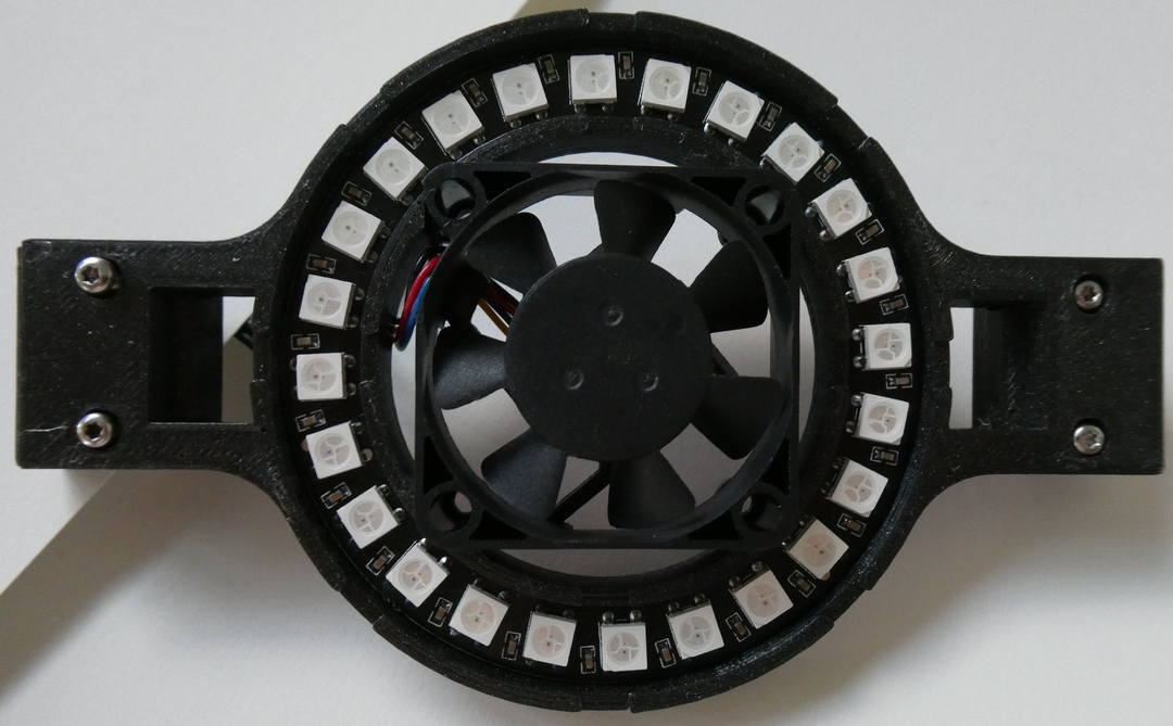
Solder the wires to the LED ring through the hole in the back:

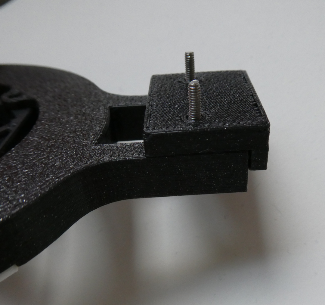
Snap the Ring Spacer to the LED ring. The spacer is required because otherwise the Ring would be obstructed by the USB ports of the Raspberry Pi:
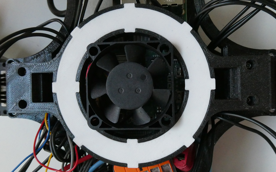
Push the Ring cover on top of the Ring, no glue required as friction keeps everything in place.
Don’t forget to connect the LED ring and the Fan to the Raspberry Pi. Screw the RingBar on top of the robot. The result should look something like this:
And with this, the assembly of Lepta is completed.